Routemaster Braking System
Please note these pages are provided for general information and should not be used as a technical reference on how to repair, maintain or otherwise alter the vehicle’s braking system.
The London Transport Routemaster uses a pressurised braking system which attains pressures in excess of 1200 psi and so must be treated with the greatest of respect and only competent people must work on it. If in doubt, DON’T !
We have to thank Steve Newman of Ensign Bus for arranging our visit to Ensign’s premises in Purfleet which are fully equipped for the repair and maintenance of Routemaster ’buses and also "RM Jack" an employee of Ensign who spent the whole afternoon with us explaining the intricacies of the Routemaster Braking system.
He is an absolute fountain of knowledge on the vehicles having spent over 15 years working at an LT garage before moving over to work for Ensign.
On this page we will deal with the braking system and the "Accumulators". Basically the braking system is a pressurised hydraulic system in which the brake pedal controls the flow of hydraulic fluid to the wheel cylinders which in turn push the shoes onto the brake drums and stop the vehicle.
The system is dual circuit (front/rear) pressurised by an engine driven pump which was originally mounted on the gearbox and belt driven off the input shaft. Later engine transplants, notably Scania, saw this pump move to the engine. In the event of engine failure there are two hydraulic accumulators which maintain the braking system pressure for at least 12 applications. A well maintained system in perfect condition can provide 20 applications.
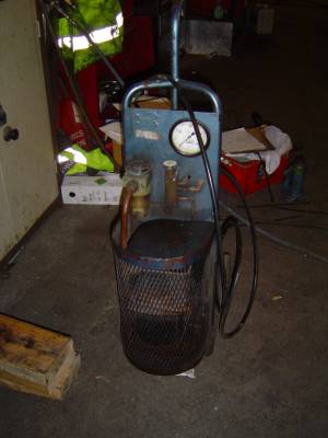
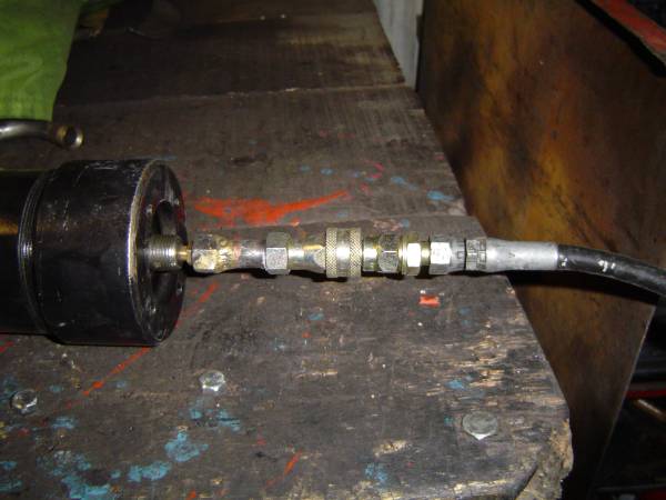
These accumulators need to be pre-charged with air at 550 psi ±50 psi in order to provide the "spring". This is normally done using an "intensifier" which is an air powered air pump ( a bit like the steam powered Westinghouse pump used on locomotives to provide air powered train brakes). This has a final stage capable of producing the 600 psi needed and stops dead when the supply air is removed. An alternative is to use a cylinder of Nitrogen gas.
 |
 |
|
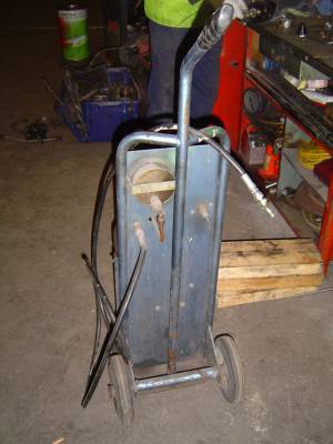
| The Intensifier - Front view | The back of the Intensifier (hose is output) | |
|
||
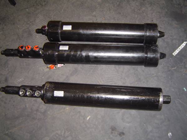
| Accumulators; Top: original front, Middle: original rear & Bottom: "Titan" version rear accumulator | ||
|
||
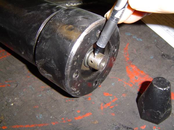
| When venting accumulator gently loosen Schrader valve body (not present) so air vents through side hole | ||
|
||
| Precharging the Accumulator; Schrader valve is the brass bit between hose and accumulator | ||
|
||
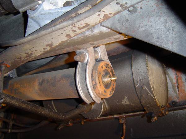
| Rear Accumulator as fitted (Dust cap removed for charging revealing Schrader Valve). | ||
|
||
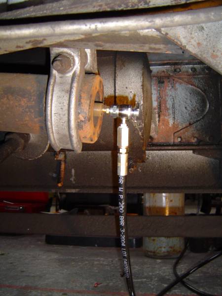
| Charging rear accumulator, in our case, with Nitrogen | ||
Before charging the accumulator(s) the brake system MUST be depressurised because the service pressure is 700 psi, secondary over 900 psi with a base line pressure of 1000-1250 psi.
This is done by parking the ’bus on the level and chocking the wheels.
Release the handbrake and then reapply but do not release the pawl and continue to hold the lever. Pump the brake and the handbrake lever should bounce as the shoes are moved by the hydraulic pressure. Once the lever stops bouncing continue to apply the brake at least 10 more times. The hydraulic level in the storage tank should have risen above normal.
The accumulators can now be recharged. Clean both caps and listen carefully as you undo the cap. A hiss indicates the Schrader valve is leaking. This can be either the body not seating properly in the accumulator or the core not seating in the body. DO NOT OVERTIGHTEN. If the core is suspected of being faulty then get a replacement from a reputable supplier noting that this is NOT a tyre valve core. Schrader suggest part number 9914-A is suitable for this application.
Connect the intensifier hose to the Schrader valve ensuring the valve body is supported against rotation by a properly fitting spanner. Charge the accumulator to 550 psi ±50 psi (DO NOT OVERCHARGE). If the accumulators have lost gas or are really low before charging then applying the brake with the air/gas supply connected will discharge the excess oil back to tank ensuring the accumulator has a full charge. Release the pressure in the charging hose carefully ensuring the Schrader valve has resealed. Refit the protective cap hand tight only.
Repeat for the other accumulator. Note: If the ’bus is left for some time the accumulator piston can stick so the oil doesn’t compress the gas. This may be overcome by depressurising the accumulator and allowing the pump to move the piston. Recharging with air/gas and applying the brake to expell the oil can recover the situation. Bottom line: your Routemaster should be driven regulary!
In the accumulator photograph above there are three units pictured. The ’bus has two: the lower unit has the cut-out valve and supports the rear braking system. The upper unit only has one connection and is for the front brakes. There are two models of accumulator fitted to Routemaster ’buses. They both do the same job but are NOT interchangeable. The original pattern have externally screwed on ends (top and middle units in photo) and the alternative "Titan" pattern (bottom unit in photo) are quite plain. The reason they are not interchangeable is that the two units use different threads for connection to the hydraulic system. Reconditioned units are available from Imperial Engineering. If you need to depressurise the accumulator then undo the Schrader valve body sufficiently to release the air through the vent hole in the side of the fitting (see photo above). Tighten the valve back up finger tight ONLY and then use a good quality spanner to tighten further by NO MORE THAN ¼ turn.
Regularly check the hydraulic level in the tank on the offside of the ’bus. The level should be normal after the ’bus has been started and you’ve heard the distinct clunk. Loss of oil is a leak. The plunger on the brake valve is a favourite; look for moisture. If the tank needs topping up use Shell T22 which is supplied in 4 gallon lots. The whole system contains 3½ gallons.
There are hydraulic test points on the vehicle: the front and rear brake systems are on the front of the axle as illustrated below. The steering test point is on the back of the axle (see below).
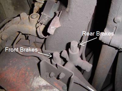 |
| Brake Test points on “Boat” Assembly (Off side front face) |
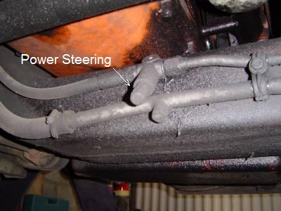 |
| Power Steering Test Point on "Boat" Assembly (rear face centre) |
Periodically (monthly) check the state of the accumulators by starting the ’bus and pressuring the braking system as normal. Stop the engine; leave the ignition on and see how many zero engine service brake applications there are; less than 9 means the accumulator(s) need recharging or the brakes need adjusting. This should be done as part of the regular inspection and lubrication.
The Routemaster has self adjusting brakes however these mightn’t always self adjust. To adjust the rear brakes park the vehicle on the level and chock the wheels. Now apply the handbrake so the pawl engages on the first ratchet. Adjust the brakes so the shoes touch the drum. Applying the handbrake fully should take two more "clicks". After adjusting the brakes test to ensure they are NOT dragging because any heat build up will decrease their effectiveness and may cause damage to seals etc. Note: So as to get the correct initial setting this manual adjustment is most important after refitting any of the drums or if any of the brake shoes or drums have been changed. Brake drums and shoes are usually changed as a matched set so little or no "bedding down" is required.
If the brakes deteriorate during the day it is possible that the drum has cracked and separated from the wheel. This only used to effect the front drums and occurred if the drum had been remachined once too often! Look for a crack on the circumference of the drum nearest the wheel.
Replacing the accumulators is a simple job if done carefully.
Depressurise the system as above and then at least ten more brake applications "for luck".
Remove the dust caps and slacken the Schrader valve bodies until the gas starts to be emitted. When fully depleted remove the brass fittings and examine for damage; replace if necessary. Fit to the new accumulators and charge these as detailed above with air (or nitrogen); refit dust caps.
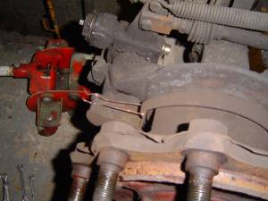
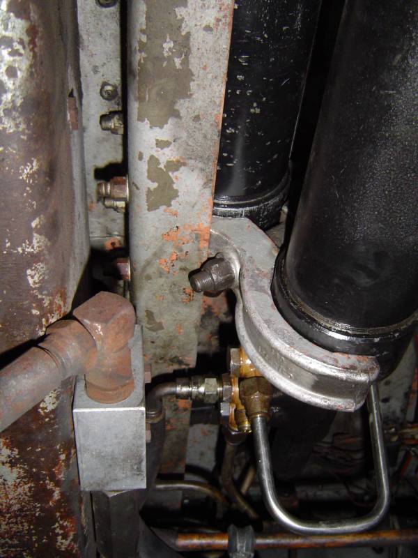 |
| Note connections; two plain banjo bolts and one through banjo (where there’s also a hose missing). |
In the picture above the rear (lower) accumulator connections are detailed (the hose supplying oil from the pump to the front accumulator is missing because it had to be replaced due to wear).
With a drip tray under the accumulator slacken and remove the hose from the through banjo bolt (¾" AF flare nut spanner); remove the banjo bolts (¾" AF socket) and put safely by in a clean container.
Slacken the yokes, rotate the rear clamp and remove the accumulator. Refit clamps and remove the two connections on the front (upper) accumulator (it may be necessary to undo the other end if the accumulator position is awkward.. Slacken the clamps again and remove the accumulator.
With the accumulators out of the way clean the top of the reservoir tank and remove the air vent (13/16" AF spanner). You may need a wide pry bar to gently lift the floor to allow the vent out. Clean the vent with "Brake and Clutch" cleaner and ensure the vent holes are clear (gas nozzle cleaners are good for this). Refit to the tank.
Clean all pipe fittings and banjos with "Brake and Clutch" cleaner; ensuring faces are scrupulously clean and that the banjo faces are flat. It is wise to check that the banjo faces are still parallel because there could be difficulty sealing them if they’re not.
Fit front accumulator to upper clamp and refit the pipes; do NOT tighten at this stage.
Fit the rear accumulator and, again, loosely fit the pipes. (Hint: hold the accumulator with the ports facing the ground whilst you lift it in and then rotate it when in place. This keeps the faces clean).
Adjust the accumulator positions to ensure no pipes are strained; do up the clamp bolts.
Tighten all pipe fittings finger tight plus ¼-½ turn (do NOT over tighten).
Having ensured all connections are secure and correct; start the engine and check for leaks. If none then leave to idle until the flag goes up and the pressure relief valve "clonk" has been heard. Now apply the brakes a few times. With the engine running and the system up to pressure check again for leaks with the brake off and applied (the pressures and flows change when the brake pedal is moved) - there MUST NOT BE ANY.
Stop the engine and turn back on the ignition. Test the "no engine applications"; there should be at least 9 though with good accumulators over 20 will be obtained until the flag drops. If the flag goes back up to give a couple more applications then there’s air in the system. In all probability this will work its way back to tank on it’s own. If it doesn’t then conventional bleeding techniques are used to remove it.
This process looses less than 100ml of oil so you shouldn’t need to top up the reservoir but check the levels anyway.
- HINTS
- If your Routemaster is to be laid up for more than a couple of days depressurise the system so the accumulators aren’t under stress. Remember the brakes will take a little longer to charge when restarted.
- Also if the ’bus is to be parked up for a protracted period chock the wheels and leave the handbrake OFF to stop the brake shoes "freezing" onto the drums.
- To check if you have an internal leak in the foot valve run the ’bus up to pressure and stop the engine (after the "clonk"). Turn the ignition back on and the flag should go back up immediately. Now, with the ignition still on, wait for it to drop again. We’re advised that this should take at least 30 minutes; obviously the longer it takes the better the seals in the system are. The use of pressure gauges on the test points will demonstrate the condition of the system more scientifically but this is a simple test to confirm you have a problem without the need to get under the vehicle.
- Wheel Cylinder Replacement
- When removing the nearside rear wheel brake cylinder the differential casing is in the way so the cylinder has to be disconnected from the brake slack adjuster first. With the handbrake on and the vehicle chocked remove the clevis pin from the wheel cylinder fork and unscrew the brake slack adjuster top pin. The brake slack adjuster must now be unwound which, due to the ratchet, requires using the centre square drive to move the brake actuator arm away from the cylinder. The handbrake slot should be long enough to not require the handrake to be disconnected. The cylinder can now be removed.
On re-assembly use new copper washers and do NOT over tighten. Check for leaks.
Don’t forget to check the brake slack adjustment before leaving the job
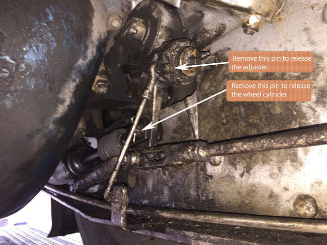 |
| Rear Brake Wheel Cylinder |
- Brake Shoe and Drum Replacement
- Put the vehicle on level firm ground; chock the diagonally opposite wheel and slacken the wheelnuts of the wheel to be worked on. Important Note: The wheelnuts on the lefthand side of the ’bus are LEFT HAND THREAD.
- Raise the vehicle and put in a safety stand. Remove the wheel(s) and inspect.
- Disconnect the brake slack adjuster activation rod from the brake slack adjuster; unwind the brake slack adjuster so the shoes are fully retracted.
- Clean the drum extraction bolt holes of crud and rust. These should be ½ UNF; two in the front drums and four in the rear. Fit high tensile bolts long enough to pull the drum off passed the thickest part of the wheel studs.
- With the drum off inspect it and the shoes for wear; distortion etc. Replace if necesary.
- NOTE: the drum and shoes are replaced as a matched set so there is less need to “bed in” the new brakes.
- If the shoes are to be removed then note they are held in place by a pivot on one side and a strong “C” spring. To release the spring there is a hole in the surface of the shoe through which a loop of wire can be inserted to lift the spring. Once lifted the stepped pin can be extracted. Carefully relax the spring and swing the shoe out of the way.
- NOTE: The front shoe pivots have castle nuts with split pins whereas the rear shoes have a figure 8 link held in with split pins.
- Refit is the reverse of the removal.
- Since the new shoes are a close fit in the new drum remember to clean the “S” cam of all debris and turn the brake slack adjuster to ensure the shoes are at their minimum setting – the drum won’t fit otherwise !
- At the rear there are four ½" UNF studs retaining the drum so make sure the extra holes in the drum are correctly aligned !
- Refit the wheel(s) and tighten the nuts ( remember – left hand thread on lefthand side of vehicle ! ).
- Remove the safety stand and lower vehicle back to the ground. Now tighten fully the wheelnuts to the correct torque of between 400 and 450 lbft.
- Reconnect the slack adjuster link rod and adjust the brakes so the shoes are just clear of the drum.
-
NOTES: After torquing the wheelnuts go round again. If any tighten further go round again. Recheck the wheelnut torque after about 50 miles ( 80km ) of use. All the brake components are heavy or very heavy so take care. Don’t forget to MANUALLY adjust the brakes until they just clear the drums. After this initial setting the automatic adjusters should compensate for the wear. The automatic adjuster will not work if the shoes are too slack a fit in the drum.
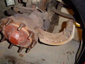 |
| Front shoe laid back for removal |
 |
| Without special tool wire is used to release spring pin |
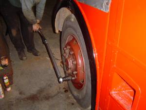 |
| Torquing up wheel nuts (note left hand thread) |
The engine mounted air compressor has NOTHING to do with the brakes. It only provides control air for the gearbox.
Happy and safe motoring.
Download a copy of the original  Lockhead Brake Manual
Note:This manual is provided “as is” for reference. The South Devon Railway accepts NO responsibility for the accuracy of the contents.
For more information contact the South Devon Railway on 0843 357 1420 or by
© South Devon Railway (RM1872) 2008-23 |  |